T-Shirt Press
T-Shirt Press
The goal of this project is to make a working T-Shirt press in the style of the Cricut Easy Press. The project is still in it’s early days but I will keep this post up-to date with the current status.
The idea came for this project when using a vinyl cutting machine. Thinking of how it would be nice to be able to make T-Shirts with with it. Link to project on github
This project is still a work in progress. the blog will be updated as progress is made.
Heated Bed
The real first step of this project was to choose an appropriate heated bed to build the press from. I searched for quite some time to find one that would be economical and still perform adequately. I explored options like getting a silicone heating mat custom made, and then affixing it to a plate of my own creation. I found this would be more work and more expensive than it might be worth in customizability. I overall ended going with a e3d High Temperature Heated Bed I went this route because it had all the features that I needed, a high max temp (200°C) and a quick heat-up time (80 seconds to 100°C), and it was fairly economical too (INC. VAT £132). This heated bed also included a resistive 104-GT2 "E3D" thermistor, so I would not have to pick one of my own.
Control systems
The next step after picking a heated bed I needed to select an appropriate microcontroller to control everything. I am currently using a STM32F429I-DISC1 because I have used it extensively in one of my courses in university. I will use this with other electronics to monitor the temperature of the hot plate and control it using a solid state relay. The following equation will be used to determine the actual temperature of the hot plate\(\frac{1}{T} = \frac{1}{T_{0}} + \frac{1}{\beta} + \ln{\frac{R}{R_{0}}}\)… The next major hurdle is how to set the target temperature I believe it will be through buttons, and then have some sort of ramp up to going faster and faster… Probably the biggest hurdle of the whole project is to implement a PID feedback loop that will control the PWM signal to the heated bed. To implement a basic method that still has some flaws is this tutorial for Arduino. To help remove some of these issues, I was fairly lost in what exactly to do. That was until I found this amazing video series on youtube and I finally understood something deeper about PID and could more completely implement it in code.
First testing
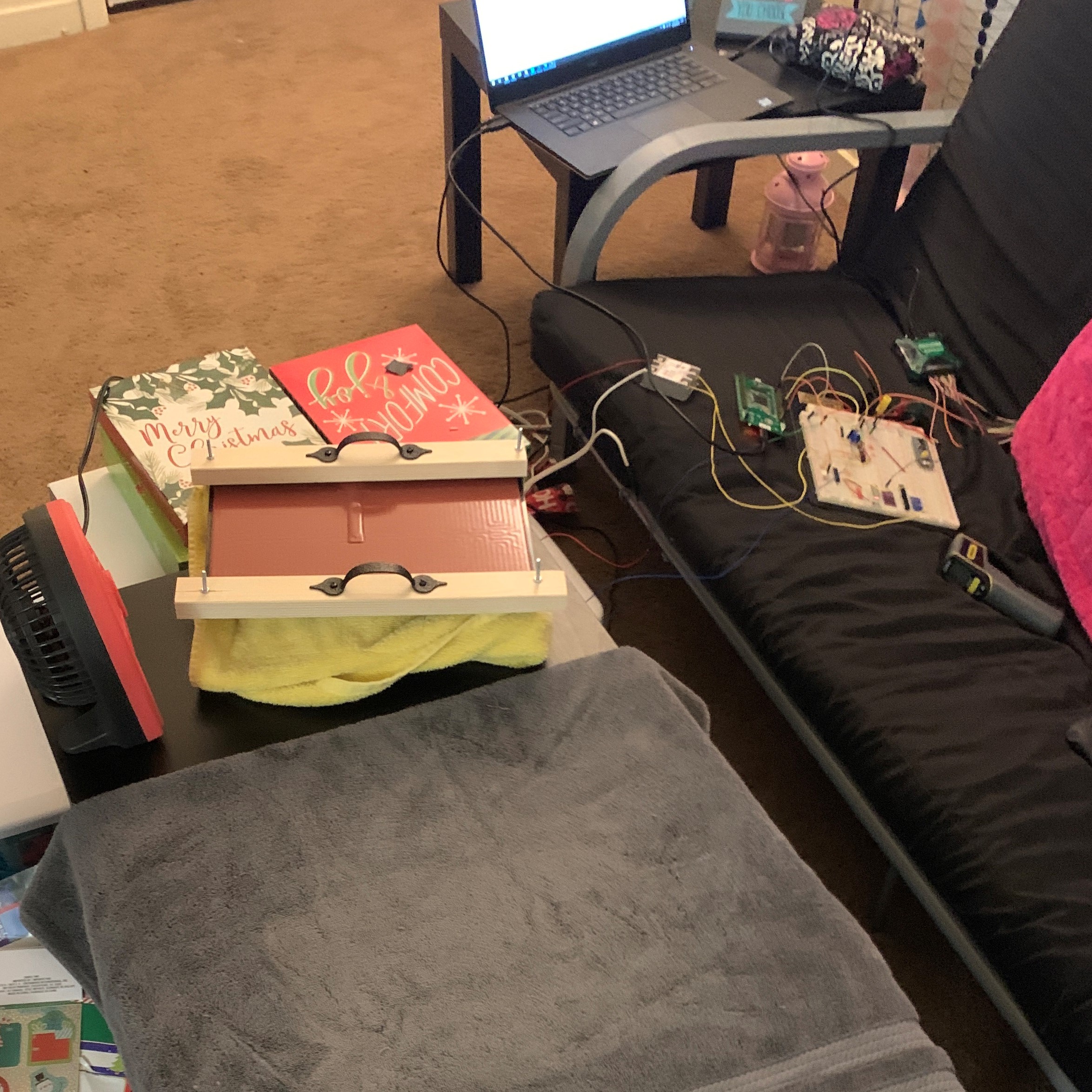
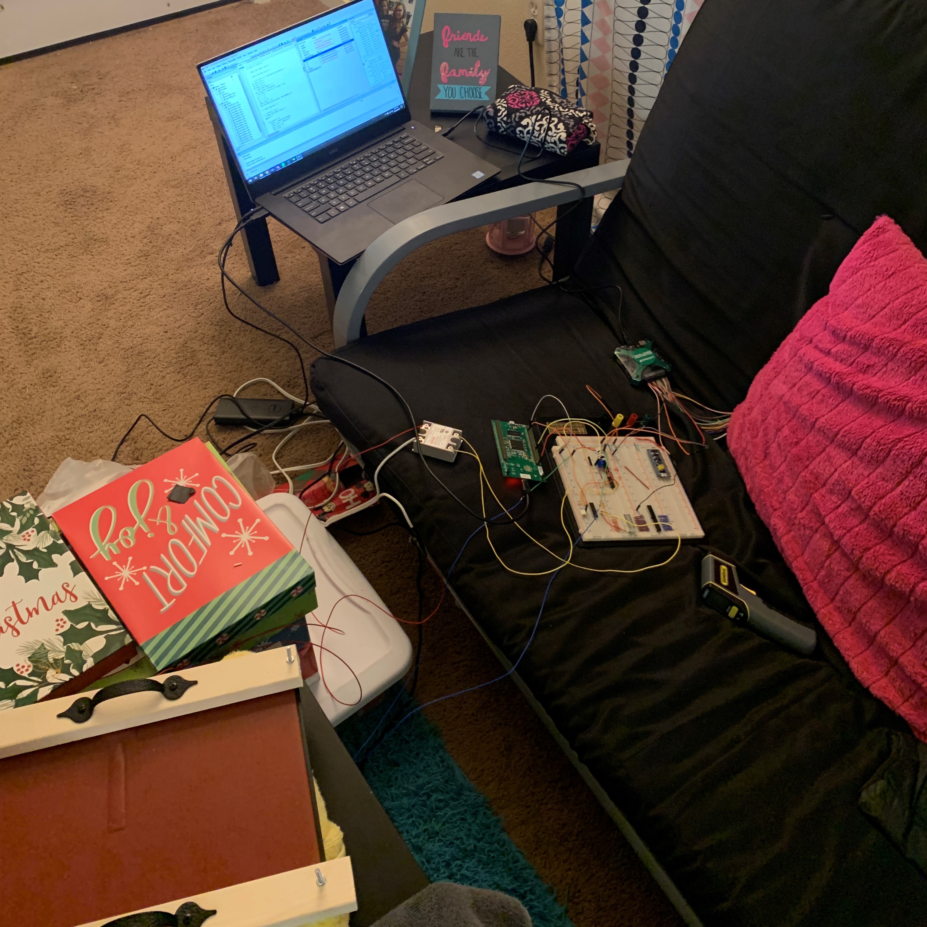
Here’s some photos from some of the first testing attempts with the press still on a breadboard. This test was a great success as you can see from the photos! We, my girlfriend Alyssa and I, made 9 shirts for our families for Christmas morning and they are pictured below.
The T-Shirt Press kept its temperature stable throughout the whole test using the PID implementation talked about above and worked almost flawlessly. One large safety concern with it in the state that it is the long screws that are being used to hold the heated bed to the wood that is being used as handles. The screws are in direct contact with the metal of the hot plate and heat to the same temperature as everything else. This could be solved using the plastic spacers that are provided with the heated plate from e3d and more screws of the correct size to clamp the wood correctly.


Next Steps
The next thing that is being worked upon is a PCB that is manufactured with the microcontroller and everything needed to run the T-Shirt press on it. This may be a lengthy process as PCB design is somewhat an art as well as a science.
As I am not a mechanical engineer or mechanical designer I can work in cad, but not to the extent to make things aesthetically pleasing, so I had a friend of mine create a design for the press. As it is very large it will be a slight issue trying to manufacture it. I think I may get it printed from a company that does 3D printing professionally.
PCB “Things”
I want to approach the pcb design and layout from at least two different angles, firstly my story about it and then specifics on the actual schematic and then the design and layout of the pcb itself. Below in these further section you can read all about exactly everything I went through from getting this designed to eventually having it manufactured.
PCB Manufacturing process
The PCBs arrived from China, and they came out perfectly, how I ordered them. It turned out that I had just forgotten to connect two nets, and I had to solder some very short wires to connect the unconnected nets. Otherwise, the circuit works fantastically! Now that we have the good news out of the way, let’s get into the process of how it was actually made. Now I’ve been into the concept of getting my own PCB manufactured for several years at this point. As far as the process itself really went, I made the decision to use KiCAD as my design suite of choice. This was the logical conclusion for me because it is free and open source. The process of going from idea to completed PCB is logical in my mind. You start with the schematic of the circuit you are tyring to make. The most awesome part of KiCAD is how many common parts and even uncommon parts are in the default KiCAD libraries. This is also where I found This video and it showed the whole process of getting a PCB manufactured from JLCPCB. I followed this video step by step almost the whole way.
The Journey
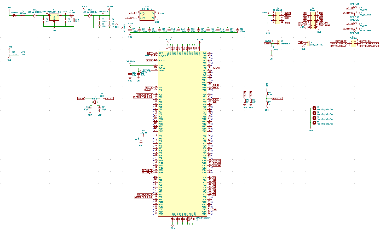
First of all this pcb has been a very, very long time coming. Furthermore, as of writing this section the pcb isn’t even done or close to done. The pcb is done now! I ended up following along with the “Very helpful video” that I linked above. It basically consists of a STM32F4 with a power supply section and lots of connectors. See the schematic below.